Solutions / Customization

A Connection
That Starts
With You.

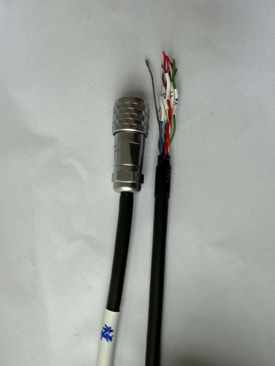
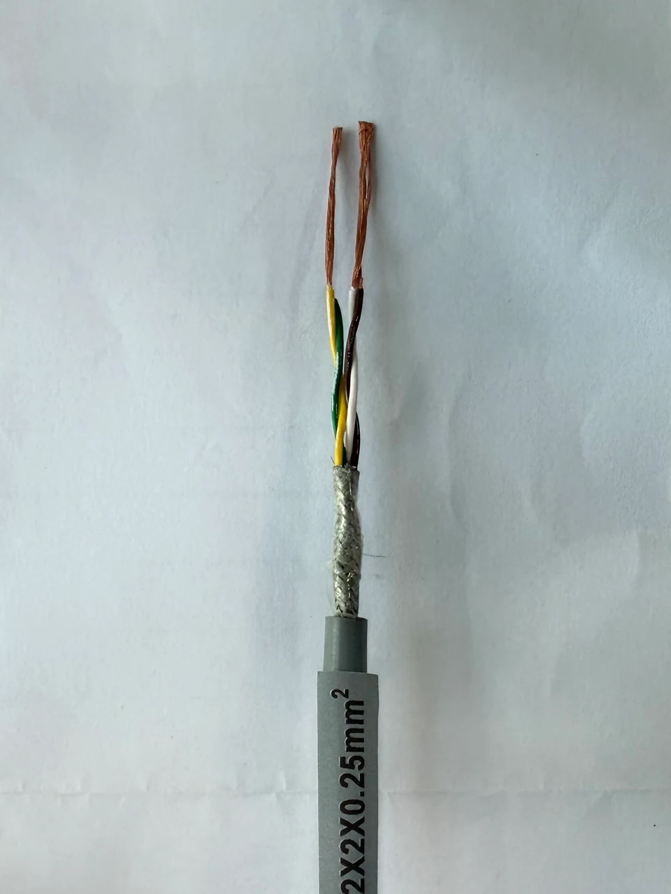
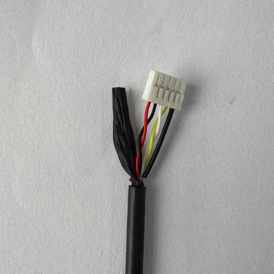
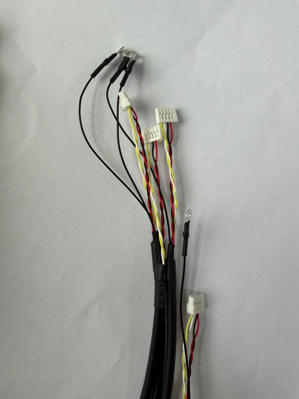
Every application arrives with its own demands: tight spaces, ceaseless motion, harsh surroundings, an unusual interface. XRYVIA begins by listening, then shapes each cable and connection around the equipment it serves. Sometimes that means reimagining the construction; sometimes a quiet shift in routing or termination changes everything. The best connections never call attention to themselves. They simply belong.

01 / Customer Stories

Where Your Work Gets Real.

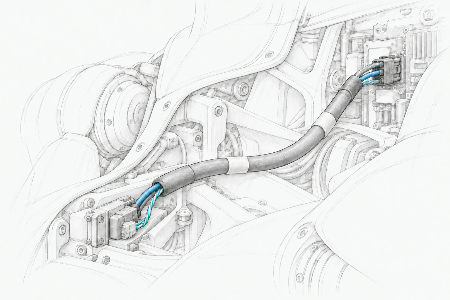
Pencil-drawn installation concept: a covered power and CAN harness curves through a humanoid robot torso, joining separate power and signal interfaces to Power Distribution Board 2.

02 / Inside the Design

Power and CAN.
One Harness.

This assembly connects power and CAN communication for Power Distribution Board 2 in a humanoid robot. Two circuit functions follow one covered route, then branch into the interfaces required at each end.

The construction brings together insulated power leads, a twisted CAN pair and a shared protective covering. The sections below explore the circuits, material choices and interfaces.

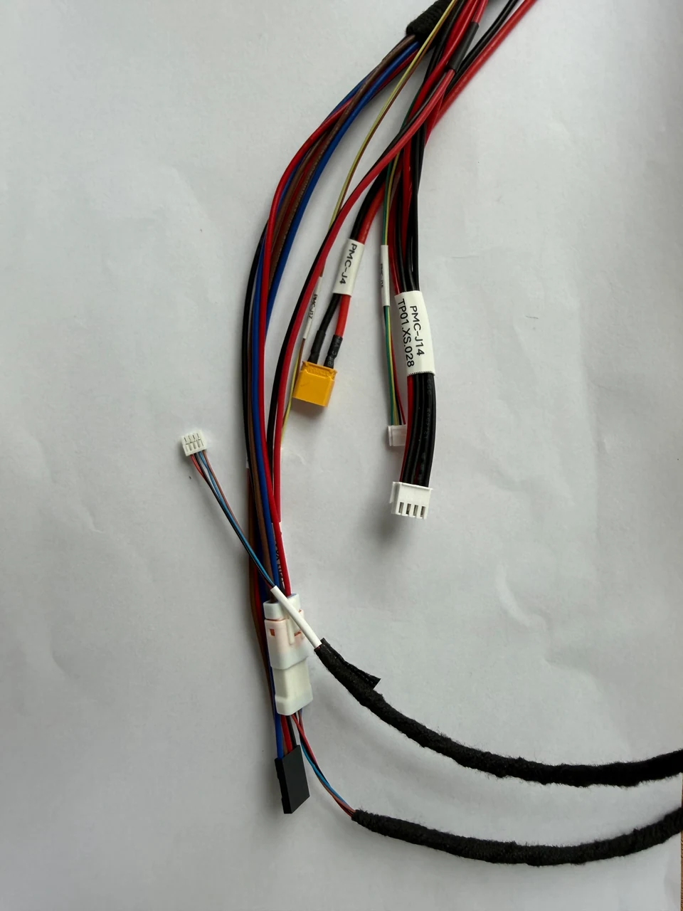
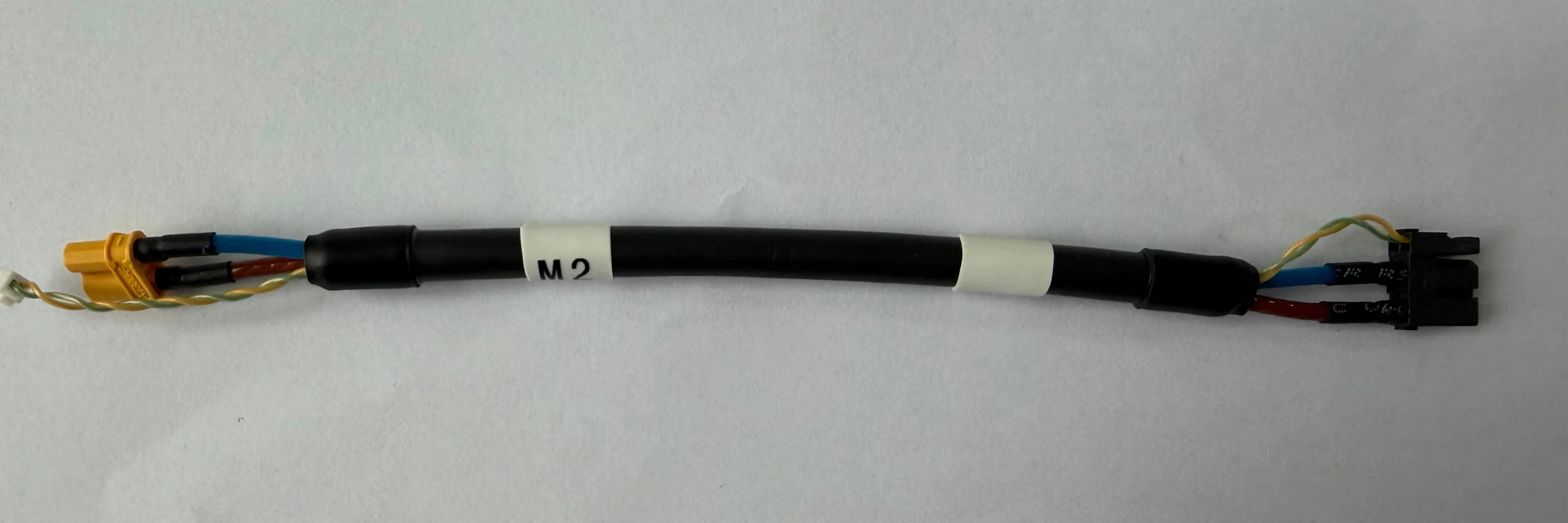
Actual humanoid-robot power–CAN harness for Power Distribution Board 2, with a black protective covering, insulated power leads, a twisted signal pair and different connectors at each end.

01 / The Circuits

Keep each circuit distinct.

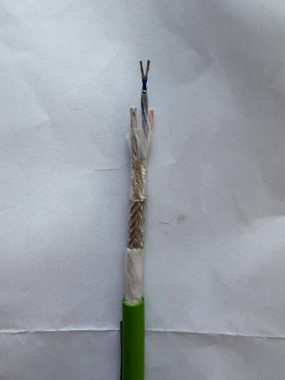
The larger red and blue power leads run beside a finer twisted pair for CAN. They share the main covered run, then separate near the terminations. Conductor sizing follows the power circuit; the CAN pair has its own routing and interface requirements.

What defines itPower requirements and the CAN interface.

02 / The Materials

Insulate and protect.

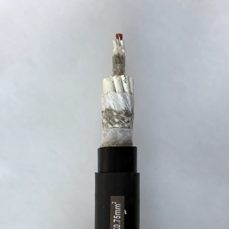
Wire insulation and the outer protective sleeve serve different roles. Insulation is selected for the circuit’s voltage and temperature; the sleeve is selected for flexibility and abrasion protection. At the connector exits, tubing size and wall thickness need to suit the wire bundle without making the transition unnecessarily rigid.

What defines itInsulation, protective sleeving and operating temperature.

03 / The Interfaces

Match the board connections.

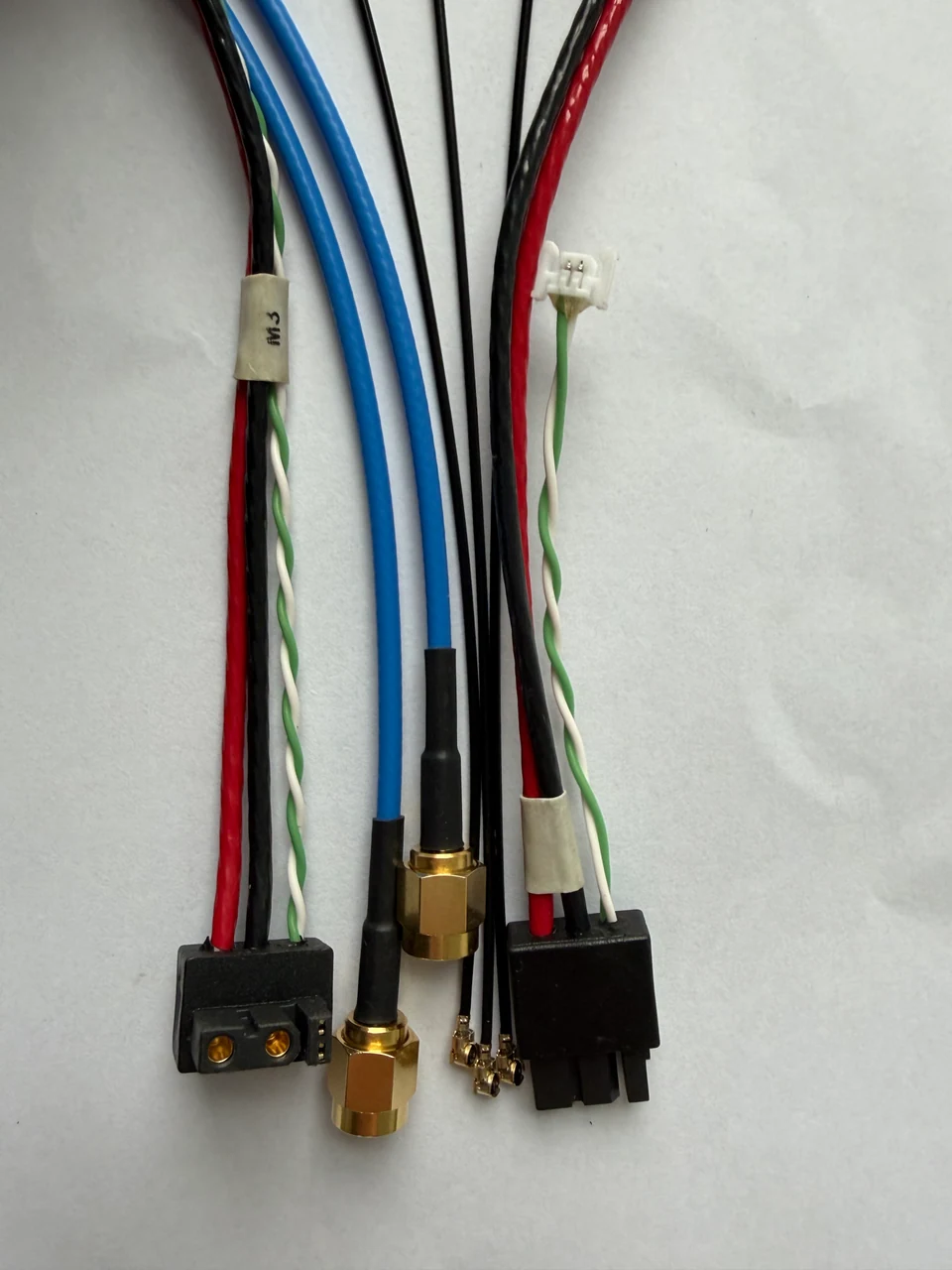
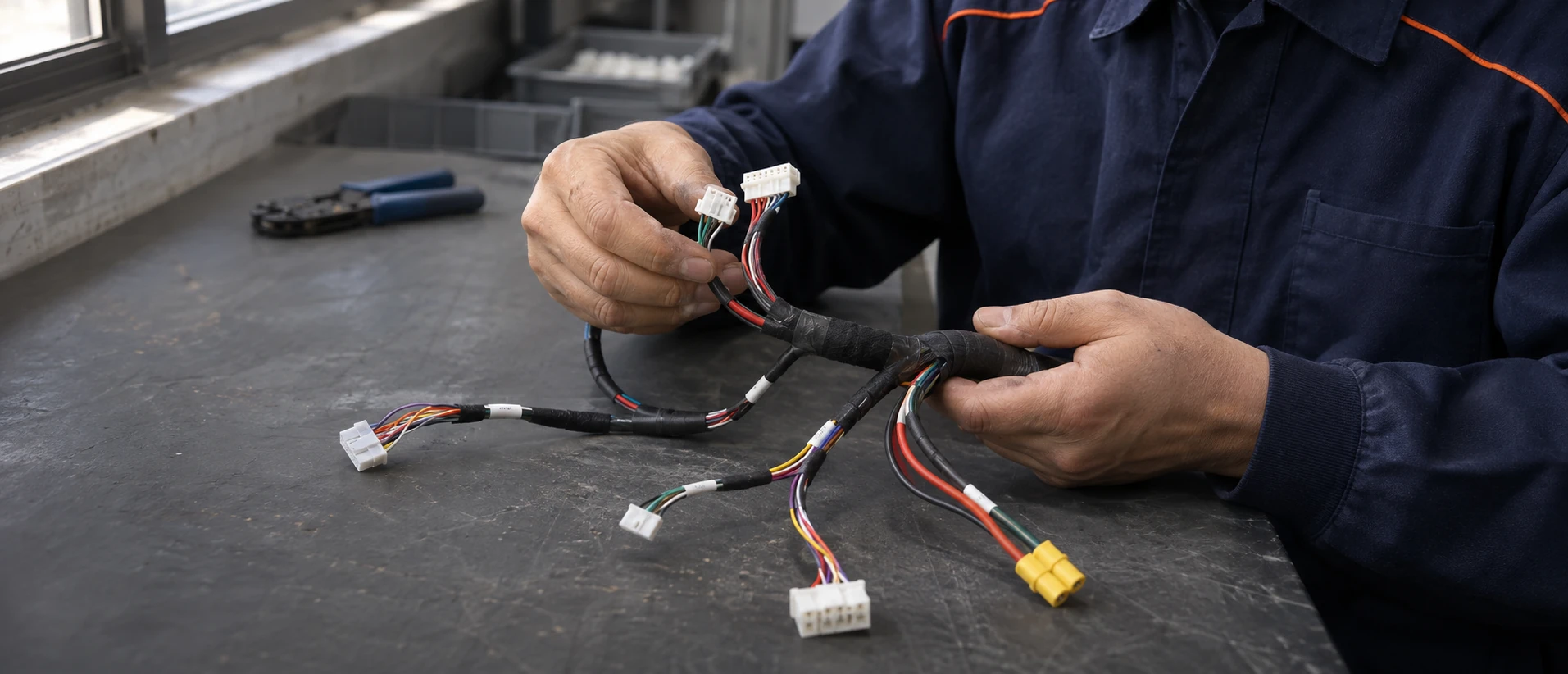
A yellow power connector and a smaller signal plug sit at one end; a black housing brings the wiring together at the other. Mating parts, contact assignments and branch lengths need to be defined together, so installation follows the board layout rather than wire colour alone.

What defines itMating connectors, contact map and branch lengths.

A Conversation, First

Your Project.
Our Starting Point.

Prepare the requirements for a technical discussion. Drawings and model references are a useful place to begin.

Prepare Your Enquiry